The simplified easiest way to Understand Frame Relay:
1. the serial interface has no layer 2 address
2. the DLCI number is the ID of the virtual cable
Look at the diagram below:
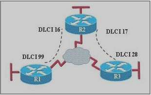
99 is the ID for the virtual cable between R1 and the Cloud.
16 and 17 are the two virtual cables between R2 and the Cloud.
28 is the ID for the virtual cable between R3 and the Cloud.
The ISP cloud connects cable 17 to cable 28, cable 16 to cable 99.
Keep in mind that there is no Layer 2 address on the Frame Relay serial interface.
Ok, that is our physical connection.
Now , let's say we have IP address configured on these routers respective interface:
R1: 192.168.123.1
R2: 192.168.123.2
R3: 192.168.123.3
Now, we need to tell the routers how to reach others.
Router R2 uses cable 16 to reach R1, 17 to reach R3
R2:
Frame-relay map ip 192.168.123.1 16
Frame-relay map ip 192.168.123.3 17
Because of the ip 192.168.123.1 to the DLCI 16 mapping, packets destined for 192.168.123.1 will be put on cable 16.
Because cable 16 is connected to cable 99 by the Frame Relay ISP, the packets will go through cable 99 and arrive at R1.
Because of the ip 192.168.123.3 to the DLCI 17 mapping, packets destined for 192.168.123.3 will be put on cable 17.
Because cable 17 is connected to cable 28 by the Frame Relay ISP, the packets will go through cable 28 and arrive at R3.
Router R1 uses cable 99 to reach both R2 and R3, because that is the only cable connected to the cloud.
R1:
Frame-relay map ip 192.168.123.2 99
Frame-relay map ip 192.168.123.3 99
Because of the ip 192.168.123.2 to the DLCI 99 mapping, packets destined for 192.168.123.2 will be put on cable 99.
Because cable 99 is connected to cable 16 by the Frame Relay ISP, the packets will go through cable 16 and arrive at R2.
Because of the ip 192.168.123.3 to the DLCI 99 mapping, packets destined for 192.168.123.3 will be put on cable 99.
Because cable 99 is connected to cable 16 by the Frame Relay ISP, the packets will go through cable 16 and arrive at R2.
Now, R2 receives this packet which is destined for 192.168.123.3.
R2 checks its own ip to DLCI mapping, and would found 192.168.123.3 is mapped to 17.
R2 then put this packets on the virtual cable 17.
The packets would go through cable 17 and cable 28, and arrive at the right destination.
R3:
Frame-relay map ip 192.168.123.1 28
Frame-relay map ip 192.168.123.2 28
Because of the ip 192.168.123.2 to the DLCI 28 mapping, packets destined for 192.168.123.2 will be put on cable 28.
Because cable 28 is connected to cable 17 by the Frame Relay ISP, the packets will go through cable 17 and arrive at R2.
Because of the ip 192.168.123.1 to the DLCI 28 mapping, packets destined for 192.168.123.1 will be put on cable 28.
Because cable 28 is connected to cable 17 by the Frame Relay ISP, the packets will go through cable 17 and arrive at R2.
Now, R2 receives this packet which is destined for 192.168.123.1.
R2 checks its own ip to DLCI mapping, and would found 192.168.123.1 is mapped to 16.
R2 then put this packets on the virtual cable 16.
The packets would go through cable 16 and cable 99, and arrive at the right destination.
By David Rupu Xiao CCIE #24177